Form Follows Path
An interactive tool for designing continuous 3D-printing trajectories.
Team
Project Focus
Role
Tools
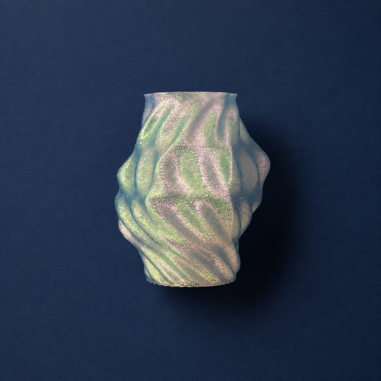
Form Follows Path is a browser-based design tool for directly authoring continuous toolpaths for vase-mode 3D printing.
Conventional workflows begin with a three-dimensional object that is later converted into machine instructions by slicing software. This project reverses that sequence. The nozzle trajectory becomes the primary design material, while the printed form emerges from the accumulation of the path.
The form preview, toolpath, fabrication feedback, and exported G-code are generated from the same geometric system, allowing design and fabrication decisions to develop together.
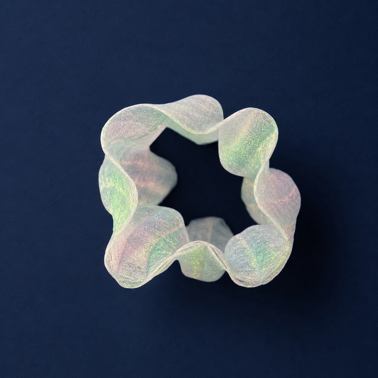
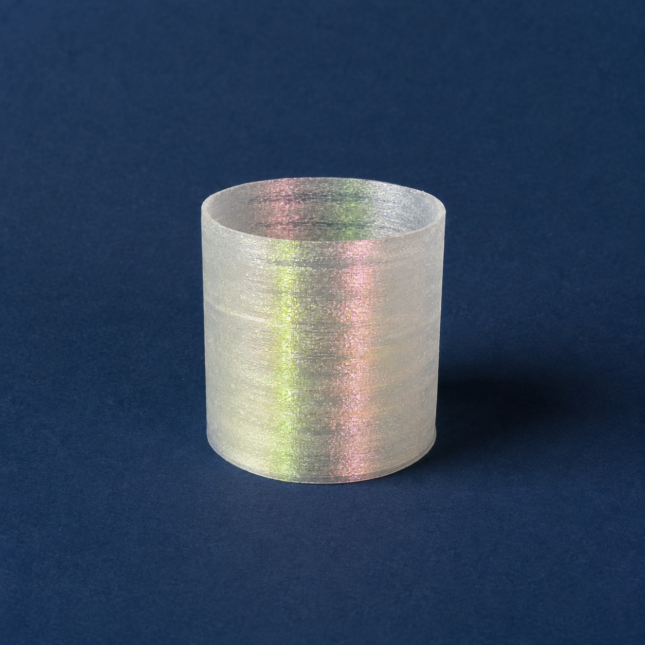
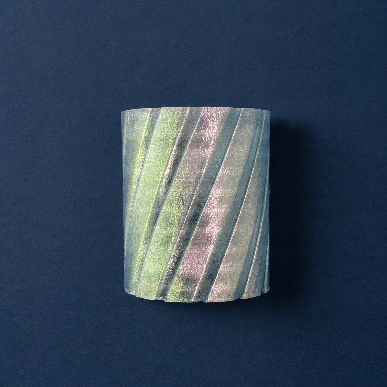
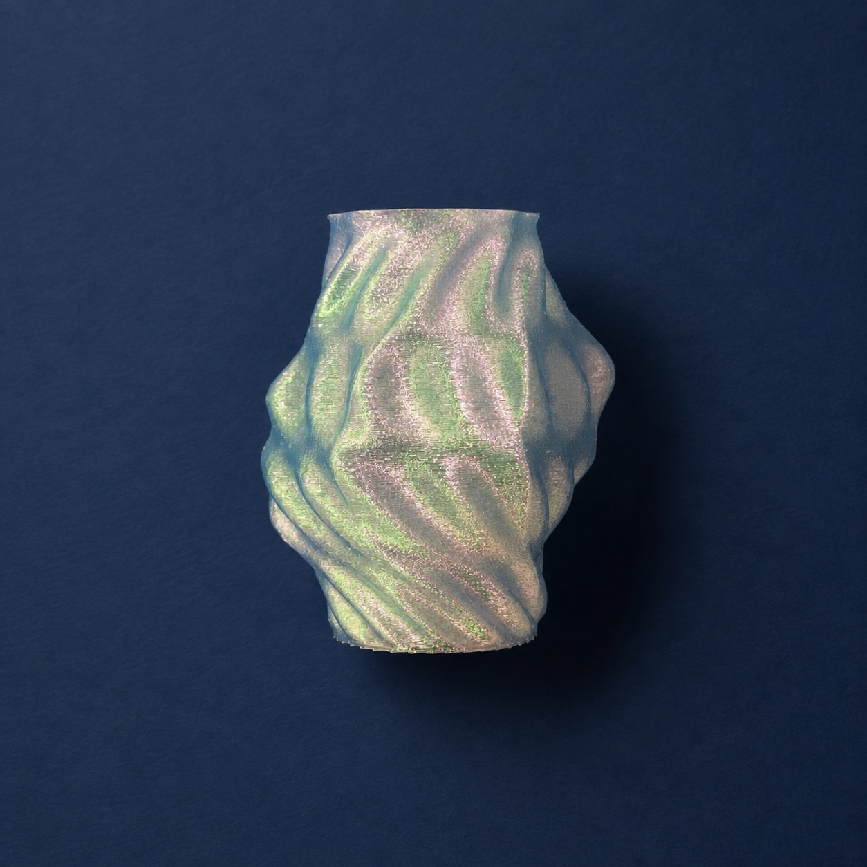
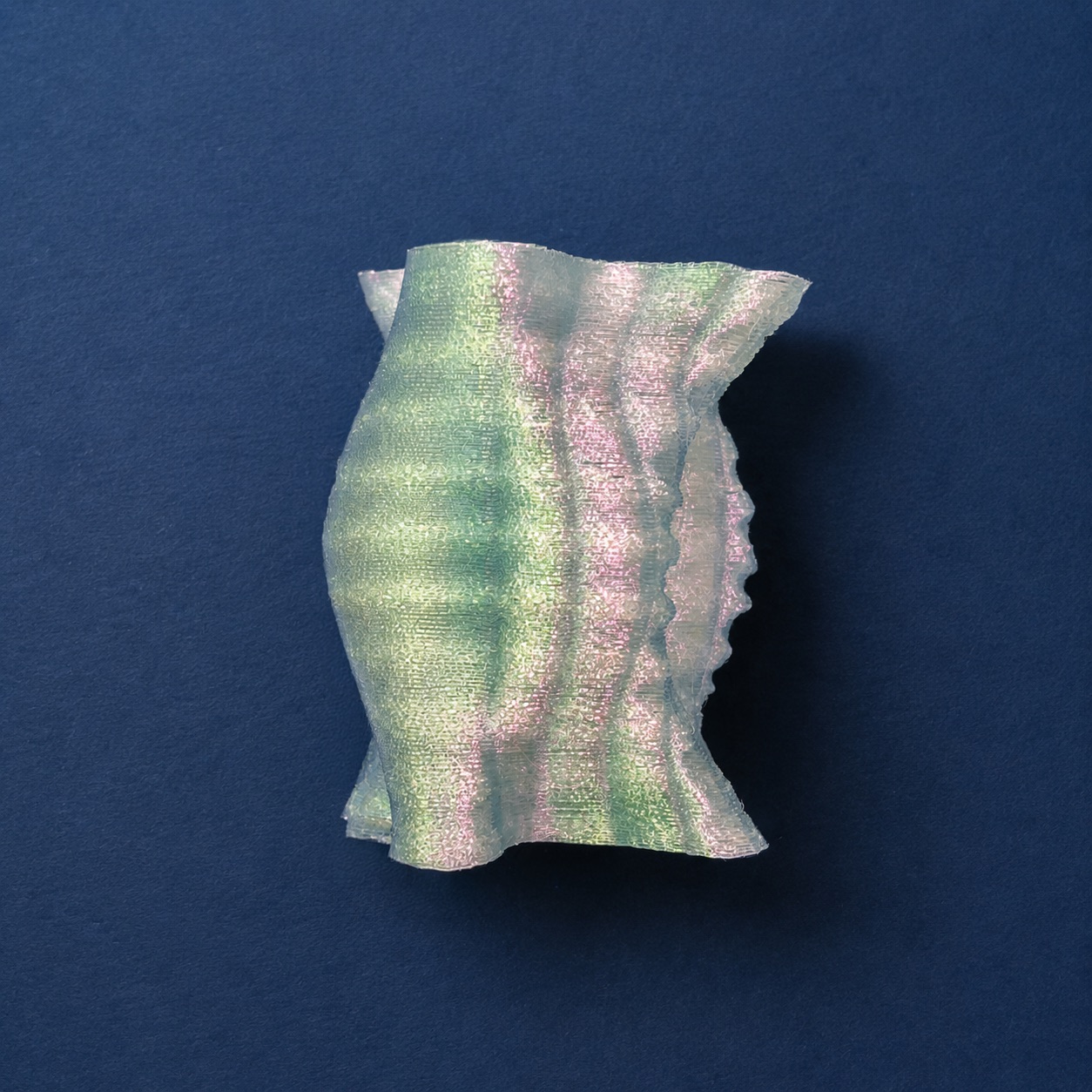
What happens when we design the path rather than the object?
How can fabrication constraints become active parameters within the design process rather than checks applied after modelling?
The project investigates how direct toolpath authoring changes the relationship between geometric intention, machine movement, and material outcome.
The project also examines how an interface can establish an interaction language for modifying three-dimensional form, and how fabrication constraints can be integrated into that process from the beginning.
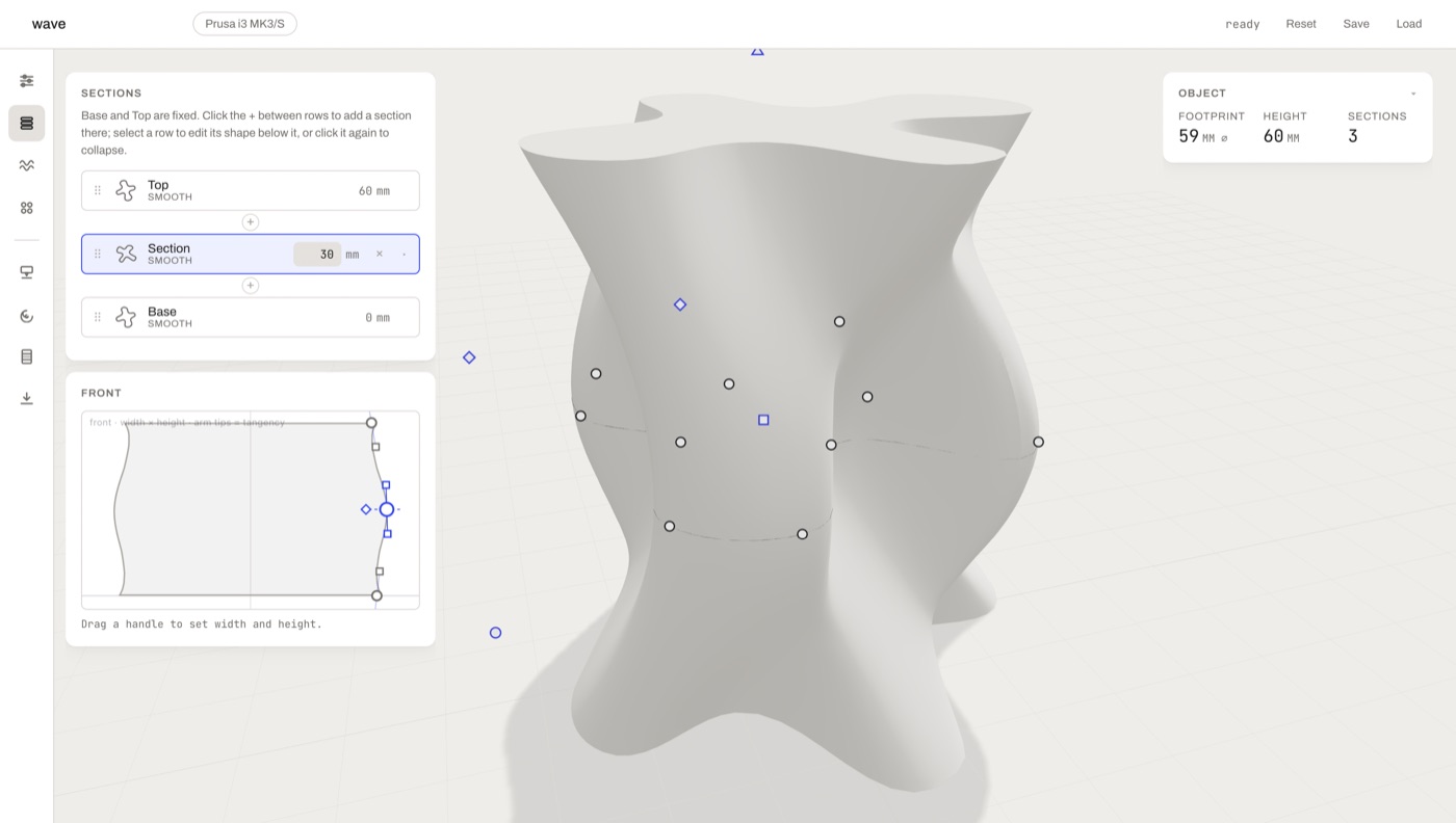
The form is developed through a series of editable cross-sections positioned along a vertical spine. Each section defines the dimensions and character of the object at a particular height.
Sections can be added, moved, duplicated, and adjusted independently. The system blends between them to generate a continuous envelope, allowing gradual transitions as well as more pronounced changes in profile.
Dimensions are defined directly in millimetres so that the geometry shown in the interface corresponds to the intended printed scale.
The cross-sections are translated into a continuous rising trajectory. Rather than producing separate horizontal layers with a visible seam, the nozzle gradually moves upward as it travels around the object.
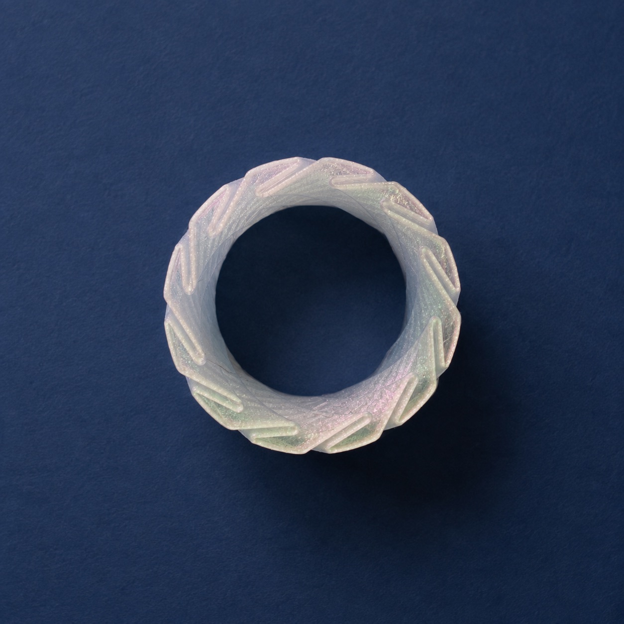
Different trajectory strategies can be applied to the same underlying envelope. A continuous spiral produces a smooth rising path, while a woven strategy introduces alternating radial movement across successive windings.
Comparing these paths on the same form makes it possible to isolate how trajectory influences:
- surface rhythm
- material distribution
- machine movement
- print duration
- the appearance of the fabricated object
The interface is organised around direct and immediate feedback. It provides several ways to modify the form and its toolpath, including editable cross-sections, profile blending, path strategies, surface modulation, and variable layer height, each of which can be adjusted while the corresponding form and trajectory update in real time.
Together, these operations form an interaction language for working with the geometry. Each action affects both the form and the fabrication path, with the results reflected across the solid preview, nozzle trajectory, print estimates, and generated G-code.
Different views make it possible to move between the object as a whole and the machine instructions used to construct it. A geometric adjustment is not shown only as a visual change to the object; its effect on the machine path and fabrication conditions also becomes visible.
The interface is therefore developed not only as a control system, but as a structured way of interacting with three-dimensional form and fabrication parameters.
Surface qualities are developed through a stack of editable modulation layers. Patterns can be applied across the entire form or painted onto selected areas.
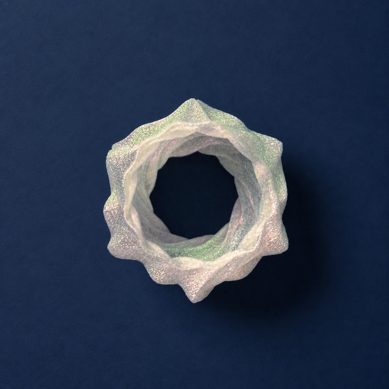
Parameters such as amplitude, frequency, direction, and intensity influence how the path moves away from the underlying envelope. Because these changes are applied directly to the trajectory, the surface is produced through nozzle movement rather than added as a texture after the object has been modelled.
Painted masks provide more local control, allowing different regions of the same form to carry different levels or types of modulation.
The painted modulation system can also influence the vertical distance between successive windings.
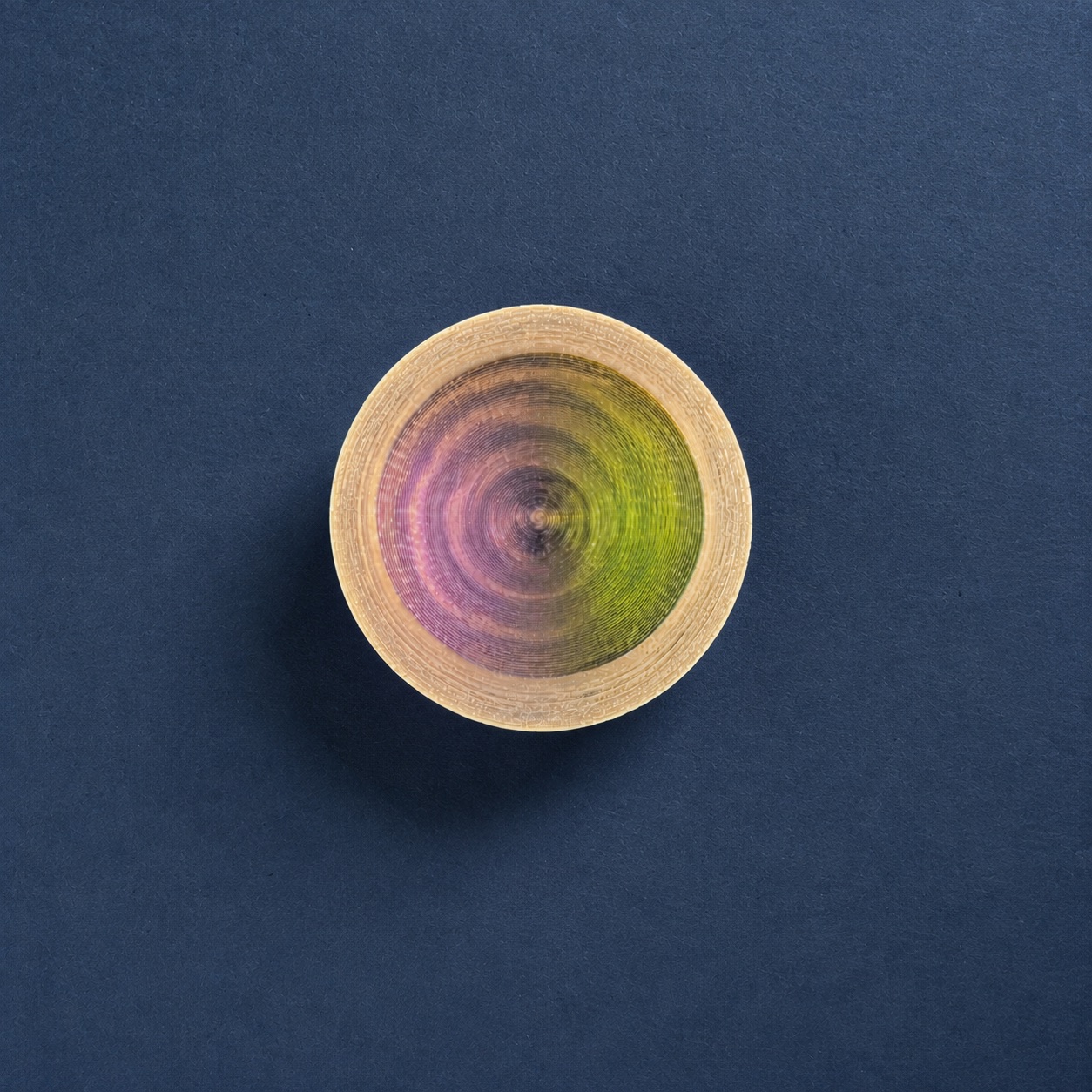
Selected areas can use smaller or larger layer heights, producing variations in surface density and visible banding. The trajectory remains continuous while the rate at which it rises changes locally.
Extrusion values are recalculated according to the changing layer height so that the path preview, material estimate, and exported G-code remain connected.
The tool evaluates the generated trajectory against selected geometric and machine-related limits.
Current checks include:
- path continuity
- overall print dimensions
- printer-bed fit
- local overhang slope
- minimum and maximum layer height
- cumulative surface deformation
- estimated material use
- estimated print time
Warnings appear while the design is being developed rather than only at export. This allows fabrication constraints to influence the form and path throughout the process.
These checks are intended as experimental design feedback, not as a complete replacement for professional slicing and G-code validation software.
Generated paths are tested through a series of controlled prints. Individual parameters can be varied while the overall envelope remains consistent, making it possible to compare the material effect of different trajectory strategies.
The tests examine where the digital preview corresponds to the printed result and where material behaviour, machine vibration, extrusion, or cooling introduce unexpected changes.
This creates an iterative process between computational authoring and physical fabrication, with the results of each print informing later geometric and interface decisions.
The current prototype supports:
- section-based form authoring
- real-scale dimensions
- continuous spiral and woven trajectories
- painted surface modulation
- variable layer height
- live form and path previews
- fabrication warnings and estimates
- direct G-code generation
Future development may include additional non-planar trajectory strategies, painted openings, explicit seam control, and spine deformation.
© 2026 Ayşe Ceren Seçkin